Hi all, I am trying to use the encoder with my nano board for rf transmission. The problem seems to be what the encoder regards as high and low. A low input voltage has a max voltage of 0.2v and a high a min of 0.8.
Should be no problem with the digital high. I believe the digital low of the nano must be greater than 0.2v as I get an invalid transmission for a low.
Can anybody suggest a solution to drag the low to below 0.2v?
Not sure what you think the problem is? From the datasheet...

Are you saying your Nano is > 0.2v when sending a low output?

That is what I am saying 'red car'. The voltage from my nano is > 0.2 . When I manually connect to ground no problem. Getting invalid transmission message from receiver when connected to the nano.
Need to somehow pull down the low output to below 0.2v for valid transmission.
Hi all, I am using the ht12e encoder connected to a digital output pin of my nano board. The specification for a low of the ht12e is less than 0.2v.
The ht12d decoder is giving a invalid transmission signal. I believe this may be due to the digital out low voltage being greater than 0.2v.
Does anybody know the digital low voltage of the nano board. And perhaps the digital high voltage. If I know these I may be able to use a resistor voltage divider to make the output compatible with ht12e.
Based on

Looks like max output voltage value of 0.9v. You could put a silicon diode between the GPIO pin and the HT12E... should have voltage drop of ~0.7v
Why did you create a 2nd post?
If you really measure such a voltage this means that you overload the output and need a signal amplifier.
You seem to misunderstand the data sheets. It states that the ht12e max LOW voltage is 0.2*Vdd = 0.6V @ 3V Vdd or 1V @ 5V Vdd.
Also the controller data sheet lists the max output voltage at the max output current. Connected to ordinary logic inputs there is no significant current flow so that the output voltage stays close to GND or Vcc.
Perhaps there exist more misunderstandings. Please provide a circuit diagram of your project. No photo nor Fritzing please!
It is here:
![]()
VOL = 0.9V means: if I assert LOW on an output pin and allow the pin to sink 20 mA current from external source, then it is guaranteed that the logic level of the pin will not exceed (0.9V is the maximum) 0.9V under the condition that supply voltage is 5V and chip's internal temperature is 850C.
Which pin of the Nano? Connected to which pin of the HT12e?
Hi Golum, I think I have it now. I have to use a 5v source and a resistor say 250 ohms for 20ma and apply the low output of 0.9v to the base of the resistor. The resistor is connected at one end to 5v and at the other end to the 0.9v output of the nano which is also connected to a data pin of the ht12e encoder for a low transmission.
The ht12e has a low input maximum of 1v. So the 0.9v should be accepted as a low by the ht12e. It is no good applying the low directly to the ht12e.
What does Vil=1.5v mean?
data sheet for the encoder:
shows these values

Peter, you are WAY off track. Provided you connect the encoder supply (Vdd to +3.3 or +5V, and Vss to 0V GND) the HT12e is ALREADY compatible - you DONT need to draw 20mA and you DONT need to change the voltage levels.
My link below explains what Vil and Vih are.
I have merged your cross-posts @petercl14 .
Cross-posting is against the Arduino forum rules. The reason is that duplicate posts can waste the time of the people trying to help. Someone might spend a lot of time investigating and writing a detailed answer on one topic, without knowing that someone else already did the same in the other topic.
Repeated cross-posting can result in a suspension from the forum. I see you have been warned previously about this.
In the future, please only create one topic for each distinct subject matter. This is basic forum etiquette, as explained in the "How to get the best out of this forum" guide. It contains a lot of other useful information. Please read it.
Thanks in advance for your cooperation.
1 Like

How is the controller input voltage related to the encoder input voltage?
I have just posted the electrical characteristics of the IO pins of the ATmega328P MCU at Vcc = 5V and AT = 850C. It is now up to the user how to use this information to meet his restrictions particularly to accommodate noise margin.
Controller output is the input to encoder and vice versa.
If you look at post 11 you will se I have given a reference for the information I provided.
an image of part of an unknown data sheet isnt much use.
I'm aware the nano has Vsubscript IL = 1.5V
However - more usefully
from the ATMEGA 328 data sheet 2020 (note this info is referenced)
https://www.mouser.co.uk/datasheet/2/268/ATmega48A_PA_88A_PA_168A_PA_328_P_DS_DS40002061B-1900559.pdf
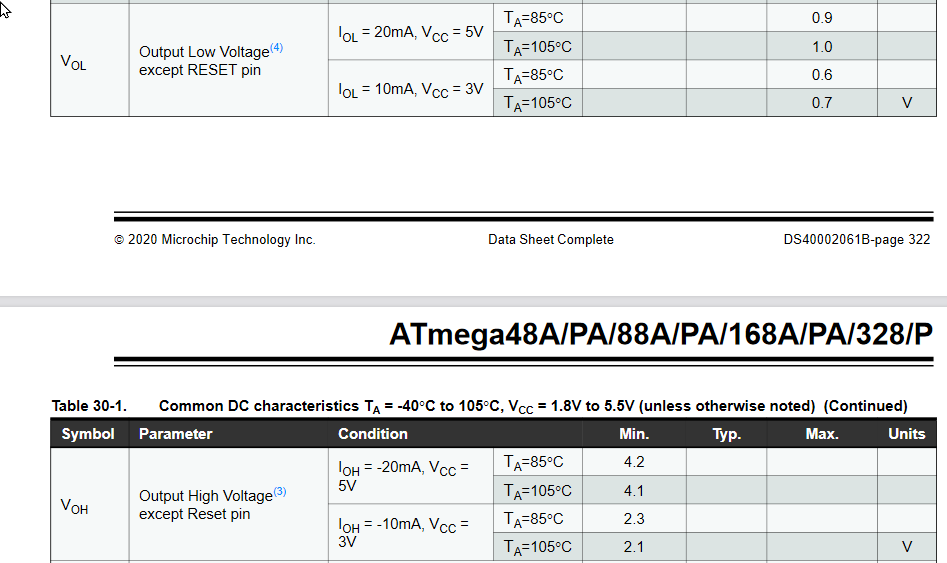
and as I said these are compatible with the encoder requirements
This topic was automatically closed 180 days after the last reply. New replies are no longer allowed.