British Aerospace Hawk Mk. 51 Construction Guide - Velocity-RC.com
British Aerospace Hawk Mk. 51 Construction Guide - Velocity-RC.com
British Aerospace Hawk Mk. 51 Construction Guide - Velocity-RC.com

Create successful ePaper yourself
Turn your PDF publications into a flip-book with our unique Google optimized e-Paper software.
BAe <strong>Hawk</strong> <strong>Mk</strong>. <strong>51</strong> : 70mm Sport Jet<br />
<strong>Construction</strong> <strong>Guide</strong> v1.3<br />
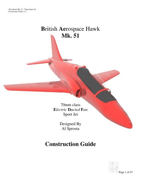
<strong>British</strong> <strong>Aerospace</strong> <strong>Hawk</strong><br />
<strong>Mk</strong>. <strong>51</strong><br />
70mm class<br />
Electric Ducted Fan<br />
Sport Jet<br />
Designed By<br />
Al Sprosta<br />
<strong>Construction</strong> <strong>Guide</strong><br />
Page 1 of 47
BAe <strong>Hawk</strong> <strong>Mk</strong>. <strong>51</strong> : 70mm Sport Jet<br />
<strong>Construction</strong> <strong>Guide</strong> v1.3<br />
Thank You and Introduction:<br />
Thank you for your purchase of the ‘Mr. Boogie’ designed <strong>British</strong> <strong>Aerospace</strong> <strong>Hawk</strong> Sport Jet.<br />
This model of the <strong>Hawk</strong> was born out of a desire to have a large size BAe <strong>Hawk</strong> that was reasonably scale, and<br />
fit <strong>com</strong>fortably in the 70mm electric ducted fan class.<br />
Sophisticated CAD tools were employed in the development of this model. This allowed for the optimization of<br />
‘model sized’ flight characteristics, as well as preserving the lines that make the <strong>Hawk</strong> such a beautiful subject.<br />
This model utilizes fiberglass <strong>com</strong>posite molding technology, greatly reducing the time required by the builder<br />
to get the aircraft ready for flight.<br />
I hope that you enjoy this <strong>Hawk</strong> model, as much as I enjoyed designing it.<br />
Many Happy Landings,<br />
Al ‘Mr. Boogie’ Sprosta<br />
Page 2 of 47
BAe <strong>Hawk</strong> <strong>Mk</strong>. <strong>51</strong> : 70mm Sport Jet<br />
<strong>Construction</strong> <strong>Guide</strong> v1.3<br />
Disclaimer:<br />
BY ASSEMBLING AND OPERATING THIS MODEL YOU ASSUME FULL RESPONSIBILITY FOR<br />
YOUR ACTIONS<br />
This aircraft is not a toy. This is a high performance radio controlled jet aircraft model that if not operated<br />
responsibly could result in serious injury to you and others. The designer, manufacturer and distributors cannot<br />
control how you assemble this model, what equipment you choose to outfit it with, or how you choose to pilot it<br />
and can assume no liability whatsoever for any damages that may occur when you fly your aircraft.<br />
By assembling this model, you are agreeing to indemnify and hold blameless the manufacturer and/or his agents<br />
from any and all torts and liability associated with the use of this product. For your safety and the safety of<br />
others, please operate your model according to the laws and regulations governing model flying in the country<br />
of use.<br />
Precautions:<br />
This plane is capable of high speeds. If you are unsure of your ability or have never flown a radio controlled<br />
aircraft before, please seek the help of an expert. It is highly re<strong>com</strong>mended that you be a member of the AMA<br />
(Academy of Model Aerodynamics), BMFA (<strong>British</strong> Model Flying Association) or similar organization<br />
depending on your country of use.<br />
Notes:<br />
A web discussion related to the development of this aircraft can be viewed at the following address:<br />
http://www.rcgroups.<strong>com</strong>/forums/showthread.phpt=59<strong>51</strong>17<br />
Page 3 of 47
BAe <strong>Hawk</strong> <strong>Mk</strong>. <strong>51</strong> : 70mm Sport Jet<br />
<strong>Construction</strong> <strong>Guide</strong> v1.3<br />
Taken from Wikipedia, the free encyclopedia<br />
The BAE Systems <strong>Hawk</strong> is a <strong>British</strong> single engine, advanced jet trainer aircraft. It first flew in 1974 as the<br />
<strong>Hawk</strong>er Siddeley <strong>Hawk</strong>. The <strong>Hawk</strong> is used by the Royal Air Force, and other air forces, as either a trainer or a<br />
low-cost <strong>com</strong>bat aircraft. The <strong>Hawk</strong> is still in production with over 900 <strong>Hawk</strong>s sold to 18 customers around the<br />
world.<br />
The <strong>Hawk</strong> 50 was the original export trainer version, and offered a limited attack capability. Finland, Indonesia<br />
and Kenya ordered 89 of this variant.<br />
<strong>Hawk</strong> <strong>51</strong> - Export version for the Finnish Air Force.<br />
<strong>Hawk</strong>s <strong>51</strong>A - Seven <strong>Hawk</strong>s were sold to Finland as part of a follow-on order.<br />
<strong>Hawk</strong> 52 - Export version for the Kenyan Air Force.<br />
<strong>Hawk</strong> 53 - Export version for the Indonesian Air Force.<br />
Page 4 of 47
BAe <strong>Hawk</strong> <strong>Mk</strong>. <strong>51</strong> : 70mm Sport Jet<br />
<strong>Construction</strong> <strong>Guide</strong> v1.3<br />
MODEL SPECIFICATIONS:<br />
Scale:<br />
Length:<br />
Span:<br />
Minimum Power requirements*:<br />
Weight w/battery*:<br />
approx 1/10 full scale<br />
46in (1168mm)<br />
37in (940mm)<br />
800 Watts<br />
up to 75oz (2126g)<br />
*Prototype Setup (as initially flown):<br />
Controls: Aileron, Elevator, Rudder, Steering, Retracts and Flaps.<br />
Battery: 4S 3700mah Lipo weighing 13.5oz (383g)<br />
RADIO/ELECTRONIC REQUIREMENTS:<br />
Minimum: 4 channel radio (see minimum control setups)<br />
Preferred: 6+ channel radio<br />
CONTROL SETUPS:<br />
Minimum Bungee:<br />
Throttle, Aileron, Elevator<br />
Minimum Rise off Ground:<br />
Throttle, Aileron, Elevator, Steering<br />
Mr. Boogie Preferred (Full House):<br />
Throttle, Aileron, Elevator, Steering, Rudder, Flaps, Retracts<br />
Minimum Servo Requirements**:<br />
Control function qty Servo description<br />
Aileron: 2 Hitec HS-65MG (Y connected)<br />
Elevator: 1 Hitec HS-82MG<br />
Nose Steering: 1 Hitec HS-55<br />
Rudder: 1 Hitec HS-55<br />
Flaps: 2 Hitec HS-55 (Y connected)<br />
Retract valve: 1 Hitec HS-55<br />
**Substitutes are fine as long as servo torque and weight is <strong>com</strong>parable**<br />
CONTROL THROWS:<br />
Aileron: +/- 0.40in (+/- 10mm); expo 35%<br />
Elevator: +/- 0.40in (+/- 10mm) measured at the Root (on the Fuselage) Leading Edge; expo 30%<br />
Nose Steering: +/- 15 degrees<br />
Rudder:<br />
+/- 0.6in (+/- 15mm); measured at rudder base/bottom<br />
Flaps:<br />
As much downward deflection as you can get, not exceeding 55 degrees.<br />
Center of Gravity:<br />
Measured rearwards, from the front center of the wing (see page 42)<br />
4.2in - 4.4in<br />
(107mm – 112mm)<br />
Page 5 of 47
BAe <strong>Hawk</strong> <strong>Mk</strong>. <strong>51</strong> : 70mm Sport Jet<br />
<strong>Construction</strong> <strong>Guide</strong> v1.3<br />
What’s in the box<br />
Qty<br />
Description<br />
1 Fiberglass <strong>com</strong>posite fuselage<br />
1 Fiberglass <strong>com</strong>posite rear hatch<br />
1 Fiberglass <strong>com</strong>posite vertical tail<br />
2 Fiberglass <strong>com</strong>posite horizontal stabs<br />
1 Fiberglass <strong>com</strong>posite wing belly pan<br />
1 Set Fiberglass ducting (1 left, 1 right)<br />
1 Sheeted and covered right wing half, with freed aileron<br />
1 Sheeted and covered left wing half, with freed aileron<br />
1 WM400 70mm edf unit<br />
1 In-runner motor (rated to 800 Watts)<br />
Vacuum formed parts<br />
1 Canopy bubble<br />
1 Cockpit tub<br />
1 Front instrument shroud<br />
1 Rear instrument shroud<br />
2 Instrument panels<br />
2 Ejection seat backs<br />
2 Sets ejection seat sides<br />
Wood parts<br />
1 Set Nose gear formers<br />
1 Set Main gear mounting plates<br />
1 Set Fan mount formers<br />
1 Set Elevator servo mount formers<br />
1 Vertical fin spar<br />
1 Vertical fin root<br />
1 Forward wing saddle former<br />
1 Wing joiner<br />
1 Wood dowel (builder cuts into smaller pieces)<br />
1 Front canopy former<br />
1 Rear canopy former<br />
2 Cockpit tub stringers<br />
1 Cockpit tub front former<br />
2 Cockpit tub wood angle supports<br />
2 Ventral fins<br />
2 Wing fences<br />
2 Horizontal stab spacers<br />
Misc parts<br />
1 Pre-bent Steel Elevator pivot rod (1/8in diameter)<br />
2 Aileron control arms and screws (4)<br />
2 Wing mounting bolts/captive nuts<br />
2 Aileron wire push rods and EZ-connectors<br />
8 CA hinges<br />
Page 6 of 47
BAe <strong>Hawk</strong> <strong>Mk</strong>. <strong>51</strong> : 70mm Sport Jet<br />
<strong>Construction</strong> <strong>Guide</strong> v1.3<br />
What’s in the box Cont’d<br />
Wood parts visual guide<br />
Page 7 of 47
BAe <strong>Hawk</strong> <strong>Mk</strong>. <strong>51</strong> : 70mm Sport Jet<br />
<strong>Construction</strong> <strong>Guide</strong> v1.3<br />
Required to Complete*<br />
*See RADIO/ELECTRONIC REQUIREMENTS for servo re<strong>com</strong>mendations<br />
Bungee Launch/Belly Lander:<br />
Qty<br />
Item<br />
1 ESC (80Amps+)<br />
1 4S Lipo 3300+ (for included motor)<br />
____________________________________<br />
1 Radio receiver (min 4 channels)<br />
1 Servo control arm, for use as an elevator control arm. I used a surplus arm from my HS82MG package<br />
1 4-40 or 2-56 threaded pushrod and clevis connector, for elevator<br />
2 12in (305mm) servo extensions, for ailerons<br />
1 Servo Y- connector, for ailerons<br />
1 Thrust/efflux tube (Mylar or overhead transparency film)<br />
1 Bungee hook<br />
1 Bungee setup<br />
Page 8 of 47
BAe <strong>Hawk</strong> <strong>Mk</strong>. <strong>51</strong> : 70mm Sport Jet<br />
<strong>Construction</strong> <strong>Guide</strong> v1.3<br />
Required to Complete*<br />
*See RADIO/ELECTRONIC REQUIREMENTS for servo re<strong>com</strong>mendations<br />
Retractable Landing Gear:<br />
Qty<br />
Item<br />
1 ESC (80Amps+)<br />
1 BEC or separate receiver battery pack<br />
1 4S Lipo 3300+ (for included motor)<br />
____________________________________<br />
1 Radio receiver (min 6 channels)<br />
1 Servo control arm, for use as an elevator control arm. I used a surplus arm from my HS82MG package<br />
1 4-40 or 2-56 threaded pushrod and clevis connector, for elevator<br />
2 12in (305mm) servo extensions, for ailerons<br />
1 Servo Y- connectors, for ailerons<br />
1 Thrust/efflux tube (Mylar or overhead transparency film)<br />
4 12in (305mm) servo extensions for retract valve servo and steering<br />
Gear specific<br />
1 Set Lightweight pneumatic retracts rated to 4-5 lbs (2 main units and 1 steerable nose unit)<br />
1 Set Retract accessories (Small air tank, tubing, tee’s, control valve, fill valve)<br />
2 Lightweight wheels 2in (<strong>51</strong>mm) diameter; mains<br />
1 Lightweight wheel 1.25in (32mm) diameter; nose<br />
3 Wheel collars<br />
4 2in (<strong>51</strong>mm) squares of lightweight fiberglass cloth (for main gear mount area reinforcement in wing)<br />
1 0.25in x 0.5in (6mm x 13mm) cross-section, 6-7inch (152-178mm) length of hardwood stick<br />
This will be used to raise the main gear mounting plates<br />
Optional<br />
2 12in (305mm) servo extensions, for flaps<br />
1 Servo Y- connectors, for flaps<br />
2 Control horns for flaps<br />
2 Push rods and connectors for flaps<br />
1 Control horn for rudder<br />
1 Push rods and connectors for rudder<br />
Page 9 of 47
BAe <strong>Hawk</strong> <strong>Mk</strong>. <strong>51</strong> : 70mm Sport Jet<br />
<strong>Construction</strong> <strong>Guide</strong> v1.3<br />
<strong>Construction</strong> aids:<br />
Glues/Adhesives:<br />
5 and 30 minute epoxy<br />
CA thin to medium<br />
Polyurethane glue (Gorilla glue/Probond)<br />
White glue (Elmers)<br />
Canopy glue<br />
Rubber Cement<br />
Sandpaper 200 – 600 grit assortments<br />
Sanding block<br />
Painter’s masking tape (low tack)<br />
Rotary tool (Dremel)<br />
Straight edge<br />
Assorted Drill bits<br />
Extra long 1/8” drill bit (10 inches minimum)<br />
Hobby knife with #11 blades<br />
Felt tip/fine line marker (Sharpie)<br />
Cling wrap<br />
Alcohol or Acetone (for cleanup)<br />
For Fiber glassing:<br />
Laminating epoxy<br />
Microballons<br />
Epoxy brushes<br />
Mixing cups<br />
Mixing (Popsicle) sticks<br />
Scissors<br />
Rubber gloves<br />
Paper towels<br />
Page 10 of 47
BAe <strong>Hawk</strong> <strong>Mk</strong>. <strong>51</strong> : 70mm Sport Jet<br />
<strong>Construction</strong> <strong>Guide</strong> v1.3<br />
Vertical Fin Attachment:<br />
1 Start by sanding the vertical fin root outline on the fuse. To protect the surrounding areas, mask them<br />
off with low tack painters tape.<br />
*Focus your sanding on the side walls of the root outline<br />
2 Glue the ply fin root outline to the fuselage.<br />
Page 11 of 47
BAe <strong>Hawk</strong> <strong>Mk</strong>. <strong>51</strong> : 70mm Sport Jet<br />
<strong>Construction</strong> <strong>Guide</strong> v1.3<br />
3 Open the root to allow the vertical fin spar to pass through.<br />
The spar opening should be inline with the back of the smaller square panel line.<br />
*The second hole is for access to a rudder servo wire.<br />
Page 12 of 47
BAe <strong>Hawk</strong> <strong>Mk</strong>. <strong>51</strong> : 70mm Sport Jet<br />
<strong>Construction</strong> <strong>Guide</strong> v1.3<br />
4 Sand the inside lower edges of the vertical fin and glue it on with slow cure epoxy and filler. Apply<br />
epoxy to the root outline on the fuse (including the sidewalls of the ply former) and the sides of the spar.<br />
5 Clean up excess epoxy.<br />
6 Align vertically and tape in place as shown. Let fully cure.<br />
Page 13 of 47
BAe <strong>Hawk</strong> <strong>Mk</strong>. <strong>51</strong> : 70mm Sport Jet<br />
<strong>Construction</strong> <strong>Guide</strong> v1.3<br />
Wing Preparation: Servo boxes and wire tunnel (Before gluing the wing halves)<br />
As a general rule lay down a layer of masking tape for marking cut lines, locations, etc. This will keep<br />
your surfaces cleaner.<br />
1 On the bottom (flat side) of the wing mark the shown dimensions.<br />
167mm (6.57in) is the length measured along the trailing edge of the aileron for cutting.<br />
10mm (0.39in) back from the aileron cut line is the location for the center of the control horn.<br />
65mm (2.56in) is the distance measured perpendicular from the hinge line to the center of the servo arm.<br />
*The little squares mean 90 degrees or a perpendicular line<br />
2 Draw your servo box. Box dimensions are 40mm x 40mm. Place your servo on the wing with the servo<br />
arm closest to the hinge line and the arm center located at the 65mm mark. The servo body should be<br />
point toward the center of the wing. Then draw a box around the servo.<br />
3 Cut out the box with a sharp #11 blade.<br />
4 Route out a servo wire tunnel, using a long drill bit or a long (brass) tube. Tunnel dimensions are not<br />
critical as long as they intersect your servo box.<br />
Page 14 of 47
BAe <strong>Hawk</strong> <strong>Mk</strong>. <strong>51</strong> : 70mm Sport Jet<br />
<strong>Construction</strong> <strong>Guide</strong> v1.3<br />
5 On the top side of your wing half, cut a small hole (shown right) above your servo wire tunnel. This will<br />
allow you pull the servo wires once the wing halves are glued. The hole on the left is for my retract air<br />
lines.<br />
6 Using fishing line or your choice of strong thread, run a long length through the servo tunnel. It should<br />
<strong>com</strong>e through the hole on the top of the wing and out the servo box. Tape it down to make sure it<br />
doesn’t move. We’ll use it later to pull the servo leads through the tunnel.<br />
7 Repeat steps 1 to 6 for the other wing half.<br />
Page 15 of 47
BAe <strong>Hawk</strong> <strong>Mk</strong>. <strong>51</strong> : 70mm Sport Jet<br />
<strong>Construction</strong> <strong>Guide</strong> v1.3<br />
Wing Preparation: Joining the halves<br />
1 Aside from your wing halves, locate the ply wing joiner and cut a 25mm length of dowel.<br />
Joiner goes in “holes up”.<br />
Dowel aligns wing at the trailing edge.<br />
Page 16 of 47
BAe <strong>Hawk</strong> <strong>Mk</strong>. <strong>51</strong> : 70mm Sport Jet<br />
<strong>Construction</strong> <strong>Guide</strong> v1.3<br />
2 Apply slow cure epoxy to the joiner, dowel and wing halves. Press together,clean up excess epoxy and<br />
tape in place.<br />
3 Place a layer of cling film on your fuse wing saddle, near the front and rear ends.<br />
4 Attach the wing to the fuse and let the epoxy fully cure.<br />
Page 17 of 47
BAe <strong>Hawk</strong> <strong>Mk</strong>. <strong>51</strong> : 70mm Sport Jet<br />
<strong>Construction</strong> <strong>Guide</strong> v1.3<br />
Wing Preparation: Servo installation<br />
There a numerous ways to install servo’s into a wing, including glueing them in. What I will show is but one<br />
method that allows for maintenance removal and replacement of the servo. The method below assumes you are<br />
using a new servo with all of its included accessories (screws, etc.)<br />
Building a Horizontal Servo Mount<br />
1 You will need thin ply sheet (1/16in) and some balsa blocks (0.5in X 0.25in) in cross section<br />
The idea is to restrain your servo’s movement with the blocks and hold it down with the ply strip.<br />
2 Before you glue the blocks in place with epoxy, wrap your servo in a layer of cling film. Once cured<br />
your mount should have a nice slop free fit to the servo.<br />
3 Using a strip of thin ply and the screws included in your servo package, create a cap for the servo mount.<br />
Gently install the self tapping screws, remove them and drip CA into the holes to harden the threads.<br />
Page 18 of 47
BAe <strong>Hawk</strong> <strong>Mk</strong>. <strong>51</strong> : 70mm Sport Jet<br />
<strong>Construction</strong> <strong>Guide</strong> v1.3<br />
5 Glue the servo mount plate into the wing. It helps to have the servo installed into the mount so that you<br />
can line up the servo arm center with your previously created marks.<br />
6 Connect your servo extension to your servo.<br />
*I tie my extensions to my servo’s end with fishing line so that they don’t separate easily.<br />
7 Pull your servo line through to the center of the wing, using the previously installed lines.<br />
8 Install your control surface control horns, if you haven’t already done so.<br />
9 Test out your ailerons.<br />
At this point you should have installed Aileron servos and connected control surfaces. The previous steps can<br />
be repeated to install Flaps and their related servos.<br />
Page 19 of 47
BAe <strong>Hawk</strong> <strong>Mk</strong>. <strong>51</strong> : 70mm Sport Jet<br />
<strong>Construction</strong> <strong>Guide</strong> v1.3<br />
Flap Servo Install<br />
1 Installing the flap servos is similar to the aileron servo procedure. Location should be just below the<br />
landing gear (20mm).<br />
Page 20 of 47
BAe <strong>Hawk</strong> <strong>Mk</strong>. <strong>51</strong> : 70mm Sport Jet<br />
<strong>Construction</strong> <strong>Guide</strong> v1.3<br />
Elevator Installation: Servo Installation<br />
*This model uses full flying stabs to control pitch, just like the full scale <strong>Hawk</strong>. As a result of aerodynamic<br />
loads generated on the stabs, a high torque metal geared servo is re<strong>com</strong>mended for use in this model.<br />
1 Locate the 3 wooden parts that make up the elevator servo mount and dry fit the assembly (as shown<br />
below) first to be<strong>com</strong>e familiar with how it goes together. Complete assembly using CA or Epoxy.<br />
2 Place your (new) servo into the frame to test the fit. You may need to file the opening a bit to allow the<br />
servo wire to clear the opening.<br />
3 Use the screws, rubber bushings and brass parts that came with your servo to screw it to the mount.<br />
Page 21 of 47
BAe <strong>Hawk</strong> <strong>Mk</strong>. <strong>51</strong> : 70mm Sport Jet<br />
<strong>Construction</strong> <strong>Guide</strong> v1.3<br />
4 The mount is positioned such that the servo arm once installed will be on the centerline of the fuselage.<br />
*With the servo in the mount, the servo hub should be positioned closest to the rear of the mount when<br />
installed. Viewed from the speed brake opening, the assembly should be glued in the middle of the opening.<br />
You want to retain access to the servo screws, but not be so far to the rear that you interfere with the efflux tube.<br />
5 Glue the wooden mount into the fuselage via the speed brake opening, using epoxy and filler.<br />
Page 22 of 47
BAe <strong>Hawk</strong> <strong>Mk</strong>. <strong>51</strong> : 70mm Sport Jet<br />
<strong>Construction</strong> <strong>Guide</strong> v1.3<br />
Elevator Installation: Stab Installation<br />
1 For installation of the stab you will need the bent steel rod, the stabs and a servo arm from your elevator<br />
servo packaging.<br />
2 Rub down the steel rod with sandpaper to rough it up a bit.<br />
3 Insert the rod into the fuselage, even it out and mark (on the rod) the points where it exits the fuse using<br />
a marker.<br />
4 Slide the wooden spacers over the rod ends and tack glue them with CA to the fuselage stab root<br />
outlines.<br />
5 Make sure that the rod can still pivot/move freely.<br />
Attaching the First Stab<br />
6 Slide a piece of cling film over the rod up against the wood spacer.<br />
7 Apply 5 min epoxy to the rod end and slide the stab onto the rod. Check to make sure your rod marks<br />
are still visible on the other side.<br />
8 Position the stab so that it presses against the spacer, and is lined up with root outline. The rod should<br />
self adjust to match your stab positioning.<br />
9 Let fully cure. You can use tape to hold the stab in position.<br />
10 Remove the single stab/rod assembly, clean up any epoxy that may have gotten past the cling film.<br />
Page 23 of 47
BAe <strong>Hawk</strong> <strong>Mk</strong>. <strong>51</strong> : 70mm Sport Jet<br />
<strong>Construction</strong> <strong>Guide</strong> v1.3<br />
Attaching the Second Stab<br />
11 Cut off one end of the servo arm.<br />
12 Reinsert the stab/rod assembly, this time sliding your servo arm over the rod before it exits on the other<br />
side of the fuse.<br />
Page 24 of 47
BAe <strong>Hawk</strong> <strong>Mk</strong>. <strong>51</strong> : 70mm Sport Jet<br />
<strong>Construction</strong> <strong>Guide</strong> v1.3<br />
13 Slide some cling wrap over the rod up to the spacer.<br />
14 Apply 5 minute epoxy to the exposed rod end.<br />
15 Slide the second stab onto the rod, press it up against the spacer and line it up against the root outline.<br />
**IMPORTANT**<br />
16 BEFORE the epoxy fully cures, pivot the stabs (together) up and down (about 25mm) each way. Then<br />
re-align the stabs with the root outlines, making sure the trailing edges of the stabs are in line with each<br />
other.<br />
17 Once cured the stabs should pivot (together) up and down freely.<br />
Page 25 of 47
BAe <strong>Hawk</strong> <strong>Mk</strong>. <strong>51</strong> : 70mm Sport Jet<br />
<strong>Construction</strong> <strong>Guide</strong> v1.3<br />
18 Position your elevator stabs so that they are level with the fuselage. Use tape to hold in place.<br />
19 With the servo arm hanging straight down and centered on the rod.<br />
Use a Popsicle stick or similar to apply *slow cure epoxy and filler to the servo arm/rod intersection<br />
only.<br />
*I used JB weld for similar but faster results.<br />
20 Let fully cure.<br />
21 Link up your elevator servo to your stabs and try them out!<br />
Page 26 of 47
BAe <strong>Hawk</strong> <strong>Mk</strong>. <strong>51</strong> : 70mm Sport Jet<br />
<strong>Construction</strong> <strong>Guide</strong> v1.3<br />
Fan Mount Installation:<br />
1 Locate your fan mount formers and fan.<br />
2 Assemble a Right and Left set of formers as shown, using CA or epoxy.<br />
Note front formers have the steeper shoulders. It may help to mark the front supports.<br />
3 Attach the formers to the fan flanges. To get an idea of where to place the screw holes, slip the fan into<br />
the fuse mated up against the ducts, place a former under a flange and mark/trace the front edge of the fan<br />
flange onto the support.<br />
Page 27 of 47
BAe <strong>Hawk</strong> <strong>Mk</strong>. <strong>51</strong> : 70mm Sport Jet<br />
<strong>Construction</strong> <strong>Guide</strong> v1.3<br />
4 Roll a temporary efflux cone and attach it to your fan, it will help with general alignment.<br />
5 Insert the Fan and former assembly into the fuselage, and slide it as far back as it will go.<br />
6 Insert both ducts sliding them forward to mate with their respective inlet covers.<br />
Page 28 of 47
BAe <strong>Hawk</strong> <strong>Mk</strong>. <strong>51</strong> : 70mm Sport Jet<br />
<strong>Construction</strong> <strong>Guide</strong> v1.3<br />
7 Slide the Fan/former assembly forward to mate with the ducts. Use tape to hold the ducts to the fan<br />
opening or a rolled collar similar to the one depicted in the previous pictures.<br />
8 With the fan in position against the ducts. Tack glue the formers in place with CA.<br />
9 Carefully unscrew and remove the fan and ducting, taking care not to knock the formers loose.<br />
10 Reinforce the former/fuse connections with epoxy/filler.<br />
Page 29 of 47
BAe <strong>Hawk</strong> <strong>Mk</strong>. <strong>51</strong> : 70mm Sport Jet<br />
<strong>Construction</strong> <strong>Guide</strong> v1.3<br />
Cockpit & Canopy assembly:<br />
1 The cockpit frame is built on the fuselage, use cling wrap to protect your fuse from glue and markings.<br />
2 Place the front and rear canopy formers on the fuse and tape them temporarily in place.<br />
3 Drill the front former through to the fuselage, to accept locating dowels. In the case of the rear former I<br />
drilled to accept rare earth magnets.<br />
Page 30 of 47
BAe <strong>Hawk</strong> <strong>Mk</strong>. <strong>51</strong> : 70mm Sport Jet<br />
<strong>Construction</strong> <strong>Guide</strong> v1.3<br />
4 Glue 2 short lengths of dowel to the front former.<br />
6 With the front and rear former in place on the fuselage, the cockpit frame goes together as shown using<br />
5 minute epoxy.<br />
7 You may want to add small doublers (using scrap wood) to the forward tub former. See <strong>com</strong>pleted frame<br />
below.<br />
Page 31 of 47
BAe <strong>Hawk</strong> <strong>Mk</strong>. <strong>51</strong> : 70mm Sport Jet<br />
<strong>Construction</strong> <strong>Guide</strong> v1.3<br />
8 Before permanently gluing in the cockpit tub, seats, instrument panels and shrouds, you should probably<br />
trim and paint them. Leave a flange on the tub and IP covers for gluing.<br />
9 Once painted the parts drop in as shown.<br />
10 The canopy can be attached with canopy glue.<br />
Page 32 of 47
BAe <strong>Hawk</strong> <strong>Mk</strong>. <strong>51</strong> : 70mm Sport Jet<br />
<strong>Construction</strong> <strong>Guide</strong> v1.3<br />
Some Cockpit images:<br />
Page 33 of 47
BAe <strong>Hawk</strong> <strong>Mk</strong>. <strong>51</strong> : 70mm Sport Jet<br />
<strong>Construction</strong> <strong>Guide</strong> v1.3<br />
Rear Hatch Attachment:<br />
I chose to use strong magnets for the canopy hold downs. I also did the same for the rear hatch.<br />
1 Epoxy pieces of scrap balsa block at the four corners of the rear hatch. Some shaping and fitting will be<br />
required before final gluing.<br />
2 Recess and epoxy a rare earth magnet into each block so that it is flush with the fuselage when the hatch<br />
is attached.<br />
3 Install mating magnets on the fuselage side and reinforce (from the backside) with epoxy/filler to hold<br />
them in place.<br />
Page 34 of 47
BAe <strong>Hawk</strong> <strong>Mk</strong>. <strong>51</strong> : 70mm Sport Jet<br />
<strong>Construction</strong> <strong>Guide</strong> v1.3<br />
Retractable Landing Gear: Nose Install<br />
1 Cut out the nose door outline at the front (underside) of the fuse. Follow the panel lines plus 15mm at<br />
the rear of the door.<br />
2 Assemble the nose gear mounting formers as shown.<br />
Page 35 of 47
BAe <strong>Hawk</strong> <strong>Mk</strong>. <strong>51</strong> : 70mm Sport Jet<br />
<strong>Construction</strong> <strong>Guide</strong> v1.3<br />
3 The nose strut should be angled up when viewed from the side.<br />
4 Mount the retract base to the formers before gluing in place in the fuselage.<br />
5 With the strut inserted and the gear in the down position. Position the formers in the fuselage so that the<br />
strut just clears the rear edge of the door and make certain that you can access the screws to remove the<br />
retract from the mounting plate.<br />
6 Glue the formers to the fuselage using slow cure epoxy and microballoons.<br />
7 Bend your nose strut so that when your gear is retracted, the nose wheel has 1-2mm clearance with the<br />
front edge of the door opening. This will help maintain a level-to-slightly nose up attitude when the mains are<br />
installed.<br />
Page 36 of 47
BAe <strong>Hawk</strong> <strong>Mk</strong>. <strong>51</strong> : 70mm Sport Jet<br />
<strong>Construction</strong> <strong>Guide</strong> v1.3<br />
Retractable Landing Gear: Main Gear Install<br />
1 Look at the image below to see where the center of your struts should be with the gear in the down<br />
position.<br />
2 Place a protective layer of masking tape on the underside of the wing in the general locations of the strut<br />
centers.<br />
3 Place the retract bases at the noted locations using the strut centers as your reference point and trace the<br />
outline of the retract bases onto the wing.<br />
4 Align the supplied wheel well template with your previous tracing and trace the well outline onto the<br />
wing.<br />
Page 37 of 47
BAe <strong>Hawk</strong> <strong>Mk</strong>. <strong>51</strong> : 70mm Sport Jet<br />
<strong>Construction</strong> <strong>Guide</strong> v1.3<br />
Page 38 of 47
BAe <strong>Hawk</strong> <strong>Mk</strong>. <strong>51</strong> : 70mm Sport Jet<br />
<strong>Construction</strong> <strong>Guide</strong> v1.3<br />
5 Using a sharp blade carefully cut the outline away. You want to cut through the covering and the top<br />
wood skin.<br />
6 If there is foam from the wing core in your pocket, remove it.<br />
7 Reinforce the area in the wing where the retract bases will go. I used 2 layers of 3oz glass cloth squares.<br />
8 Mounting plates are provided for the retract mains, but you will need to build offset supports before<br />
attaching the mains to the wing.<br />
9 Using some hardwood blocks, I cut off sections to match the retract mains mounting plates. They are<br />
glued to the plate and act as standoff’s for the retract mains.<br />
10 The plate/blocks structure and retract gets glued into the wing. Wrap the retract base in cling film and<br />
secure it to the mount before final gluing into the wing.<br />
TIP: Insert your unbent wire struts before the glue fully sets, retract them and make sure the struts point to<br />
each other.<br />
11 If using wire struts, follow the bend guidelines provided.<br />
WARNING: The strut centers are very close to the CG, so bent leg struts are highly<br />
re<strong>com</strong>mended.<br />
Page 39 of 47
BAe <strong>Hawk</strong> <strong>Mk</strong>. <strong>51</strong> : 70mm Sport Jet<br />
<strong>Construction</strong> <strong>Guide</strong> v1.3<br />
Page 40 of 47
BAe <strong>Hawk</strong> <strong>Mk</strong>. <strong>51</strong> : 70mm Sport Jet<br />
<strong>Construction</strong> <strong>Guide</strong> v1.3<br />
Retractable Landing Gear: Steering Servo Install (pull-pull)<br />
There are numerous ways to install your steering servo. I chose to position my steering servo between the<br />
retracted nose wheel and the front of the retract cylinder, mounted to the top of the fuselage nose.<br />
I fabricated a mount for my servo that allows me to remove the servo for maintenance.<br />
1 Using some scrap balsa blocks, I constructed a mount that holds my servo in a vertical orientation.<br />
2 The mount is then glued with epoxy to the ceiling of the fuselage.<br />
3 With the gear down, pull lines are then attached to the servo arm ends and to the steering arm.<br />
Page 41 of 47
BAe <strong>Hawk</strong> <strong>Mk</strong>. <strong>51</strong> : 70mm Sport Jet<br />
<strong>Construction</strong> <strong>Guide</strong> v1.3<br />
General Component Placement and Center of Gravity<br />
Note: The CG pictured below is safely forward. You will need some up elevator trim at the specified balance<br />
point. This CG is re<strong>com</strong>mended for your first flights; you can move it back as you be<strong>com</strong>e familiar with the<br />
aircraft.<br />
You should balance the ready to fly aircraft upside down at the indicated position. If you have retracts, put them<br />
in the gear down position before balancing.<br />
The attitude of the aircraft should be level to slightly nose down.<br />
Page 42 of 47
BAe <strong>Hawk</strong> <strong>Mk</strong>. <strong>51</strong> : 70mm Sport Jet<br />
<strong>Construction</strong> <strong>Guide</strong> v1.3<br />
Without your battery, chances are your build will be tail heavy with everything installed. Your battery (and<br />
battery tray) should be located so that your craft balances at the stated center of gravity.<br />
The images below show where I chose to locate certain <strong>com</strong>ponents.<br />
Retract air<br />
tank, valve<br />
and servo in<br />
Battery<br />
and tray<br />
ESC mounted up under rear hatch vents.<br />
Receiver at the back of rear hatch opening,<br />
attached to sidewalls with Velcro.<br />
Page 43 of 47
BAe <strong>Hawk</strong> <strong>Mk</strong>. <strong>51</strong> : 70mm Sport Jet<br />
<strong>Construction</strong> <strong>Guide</strong> v1.3<br />
Test Flight<br />
* Before the first flights input 2 to 3 clicks of up elevator trim.<br />
Runway takeoff roll should be between 150 and 200 feet, depending on the weight of your aircraft and power<br />
system. Takeoffs should be into the wind (if any) at full throttle. Roll on throttle and build up speed after about<br />
150 feet, smoothly apply a small amount of up elevator. Keep your climb out gentle and gain altitude (2 to 3<br />
mistakes high), retract your gear if you wish and trim the aircraft at ¾ throttle.<br />
Make a few gentle circuits to adjust to the models handling, keep your turns large and smooth. At altitude<br />
check the stall of the aircraft, and practice slow flight to be<strong>com</strong>e familiar with the aircrafts slow speed handling.<br />
Landings are best executed with a little throttle. With throttle between ¼- ½, control your descent with throttle<br />
and use elevator to flair 1 to 2 feet above the runway.<br />
Bungee assisted launches can be done with a ramp, rail or dolly setup. Setup your bungee pull tension to equal<br />
5-6 times the models ready to fly weight.<br />
Page 44 of 47
BAe <strong>Hawk</strong> <strong>Mk</strong>. <strong>51</strong> : 70mm Sport Jet<br />
<strong>Construction</strong> <strong>Guide</strong> v1.3<br />
Page 45 of 47
BAe <strong>Hawk</strong> <strong>Mk</strong>. <strong>51</strong> : 70mm Sport Jet<br />
<strong>Construction</strong> <strong>Guide</strong> v1.3<br />
Page 46 of 47
BAe <strong>Hawk</strong> <strong>Mk</strong>. <strong>51</strong> : 70mm Sport Jet<br />
<strong>Construction</strong> <strong>Guide</strong> v1.3<br />
Page 47 of 47